
| NS 1000 | NS 500 | NS 208 | NS 204 |
 |
|||
| NS 100 | NS 50 | NS 25 | NS 5XP |
| Ausgehend davon dass TCP/IP, Routing, Switching
und dgl. Ihnen geläufige begriffe sind, werde ich hier Versuchen die
Konfiguration und Hilfestellung für die NS 100 so verständlich als
möglich zu beschreiben. Deshalb nur die NS 100, da alle NetScreen von NS 5XP bis NS 1000 auf die selbe Art und weise zu konfigurieren sind. Unterschiede bzgl. der einzelnen Produkte finden Sie unter www.netscreen.com. Alle Befehle die ich hier anführe sollten Sie mit Vorsicht genießen, ebenso auch nur dann Verwenden wenn Sie die Folgen anhand meiner Beschreibung verstehen. Hierzu gleich noch angeführt übernehme ich KEINE Garantie für etwaige Fehler oder Schäden in Ihrem Netz.
|
|
| Wichtige Befehle | Erklärung |
| netscreen | Default UserName und Default Passwort |
| get | Ansicht der System Informationen |
| set | Konfigurieren der System Informationen |
| unset | Löschen der System Information |
| save | Speichert alle Informationen |
| exit | Ende der "Telnet" Sitzung |
| clear | Löscht Dynamische System Informationen |
| reset | Neustart |
| ping | dazu keine Erklärung |
| trace-route | dazu ebenso keine Erklärung |
| exec | Ausführen von Systemkommandos |
| TIP: Testen Sie die Eingabe " get ? " und sie bekommen alle Möglichkeiten für die weitere Eingabe. Ebenso sollten Sie Testen " get system " hierbei kommen alle relevanten System Informationen, wie z.B. Ser. Nr., IP Nr., Trusted Interface IP..... |
|
| Weitere Befehle | Erklärung |
| set console time 0 | Abschalten des Autologout bei der Telnet Sitzung |
| set admin sys-ip A.B.C.D | System IP Nr. A.B.C.D = z.B. 2.2.2.20 |
| set admin sys-ip 0.0.0.0 | System IP auf 0.0.0.0 stellen und die Interfaces konfigurieren. |
| set int ? | Somit sehen Sie den nächsten Eintrag der möglich ist. z.B |
| set int trust manage-ip A.B.C.D | hierbei können Sie das Trusted Interface konfigurieren |
| get int trust | Ansicht der soeben getätigten Konfiguration |
| save config to tftp [IP VOM TFTP] [FILENAME] | Sichern der Konfiguration auf dem Rechner |
| save config from tftp [IP VOM TFTP] [FILENAME] | Rücksichern der Konfiguration vom Rechner auf die NS |
| debug flow tcp-mss | 1; Debug Modus aktiviert |
| clear db | 2; Löschen der Debug Daten die vor dem aktivieren geschrieben wurden |
| ping www.bintec.de | 3; Ping auf BinTec HP |
| get db st | schreibt alle Daten zurück die über die NS gelaufen sind |
| Esc [Taste] | Esc taste drücken um Debug zu Stoppen [UNBEDINGT zu machen] |
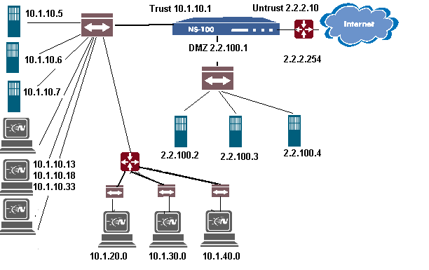
| 10.1.10.5 | Intranet Web |
| 10.1.10.6 | Corp Mail |
| 10.1.10.7 | Intranet DNS |
| 10.1.10.13 | Admin PC 1 |
| 10.1.10.18 | Admin PC 2 |
| 10.1.10.33 | Admin PC 3 |
| 10.1.20.0 | Abteilung Sales |
| 10.1.30.0 | Abteilung Support |
| 10.1.40.0 | Abteilung Marketing |
| 2.2.100.2 | Corporate Mail |
| 2.2.100.3 | Mail Relay |
| 2.2.100.4 | DMZ DNS |
Netscreen Nat Mode Konfiguration
| Befehl | Erklärung |
| set admin sys-ip 0.0.0.0 | Setzt die System IP auf 0.0.0.0 |
| set int trust nat | Aktiviert am Interface TRUST NAT |
| set int trust ip 10.1.10.1 255.255.255.0 | Vergibt IP 10.1.10.1 dem Interface TRUST |
| set int untrust ip 2.2.2.10 255.255.255.0 | Vergibt IP 2.2.2.10 dem Interface UNTRUST |
| set int untrust gateway 2.2.2.254 | Vergibt das default Gateway am Untrusted Interface |
| save | Speichern der Konfig |
Netscreen Transparent Mode Konfiguration
| Befehl | Erkärung |
| set admin sys-ip 2.2.2.1 | System IP setzen |
| unset int trust ip | Setzt am Interface Trust die IP auf 0.0.0.0 |
| unset int untrust ip | Setzt am Interface Untrust die IP auf 0.0.0.0 |
| save | Speichern der Konfig |
Netscreen Route Mode Konfiguration
| Befehl | Erkärung |
| set admin sys-ip 0.0.0.0 | Setzt die System IP auf 0.0.0.0 |
| set int trust route | Aktiviert am Interface Trust den Route Modus |
| set int trust ip 2.2.10.1 255.255.255.0 | Vergibt die IP 2.2.10.1 am Trusted Interface |
| set int untrust ip 2.2.2.10 255.255.255.0 | Vergibt die IP 2.2.2.10 am Untrusted Interface |
| set int untrust gateway 2.2.2.254 | Vergibt das default Gateway am Untrusted Interface |
| save | Speichern der Konfig |
IKE Konfiguration mit Pre-shared Key für NS100
To configure the
Netscreen Firewall for a connection
to a Netscreen Remote Client-Auto IKE Configuration with Pre-shared Key
______________________________________________________

2.
Figure
1
Figure
#2
_______________________________________________________________________________________
![]()
Figure
#3
_______________________________________________________________________________________

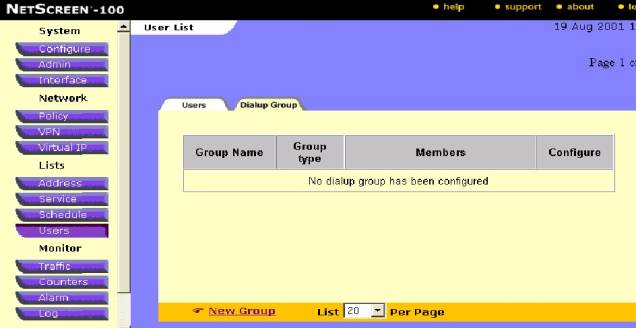
Figure #4
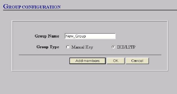
Figure #5
__________________________________________________________________________
link-(see Figure #6).

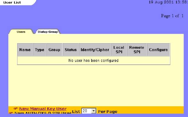
Figure #6

![]()
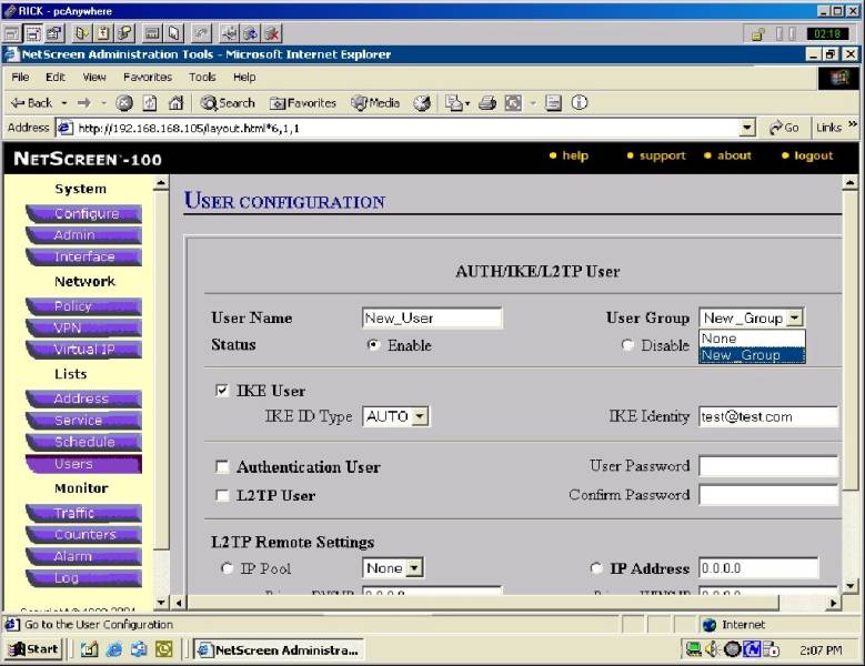
Figure #7
___________________________________________________________________________________
Note: if you are going
to require “authentication” thru
you VPN policy also fill in the “Authentication
User” check box here and create a User
password and confirm the password—Click
OK to save the USER settings. See
arrows in figure #7 above.

Figure
#8
____________________________________________________________________________________
12. Now you can Configure your Gateway screen:
a. Give the Gateway a name—e.g.”New_Dialup”
b. Select the “Dailup User “ radio button
c. Make sure you select the proper User/Group from the dropdown box
d. Select Mode Initiator—“Aggressive”
Note: All VPN with a “dynamic IP” assigned will
use “aggressive” mode whether Dialup or Box to Box.
e. Next select the desired Phase 1 Encryption and Hash Algorithms—shown is “pre-g2-des-md5”.
§ Encryption Algorithm. Select DES for minimal security or Triple-DES for highest security.
§ Hash Algorithm. Select MD5 for minimal security or SHA-1 for highest security.
§ Key Group. Select Diffie-Hellman Group 1, 2 or 5
Note: the Pre stands for “Pre-shared Key” and ‘”g2” is for the Diffe-Hellman group as above
f. Lastly, input a “Pre-shared Key” of at least 8 alpha numeric characters and no more than 54—o
not use keyboard characters such as / ! $.-the key will appear hashed in OS 2.5 or higher—
See figure #9 below.
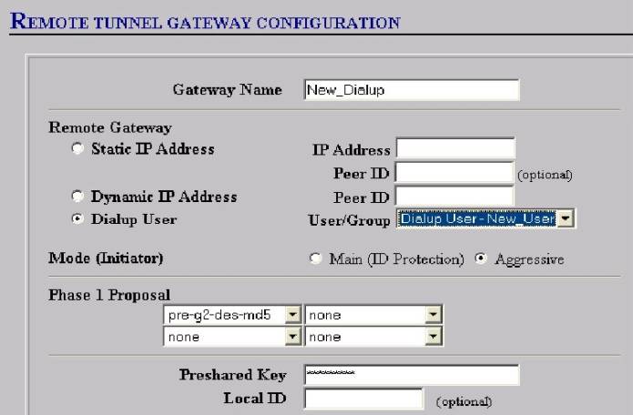
Figure #9
____________________________________________________________________________________
Click “OK” at
bottom of page to save the Gateway configuration.
This demo assumes that “Certificates” are not
chosen and used and are ignored here.
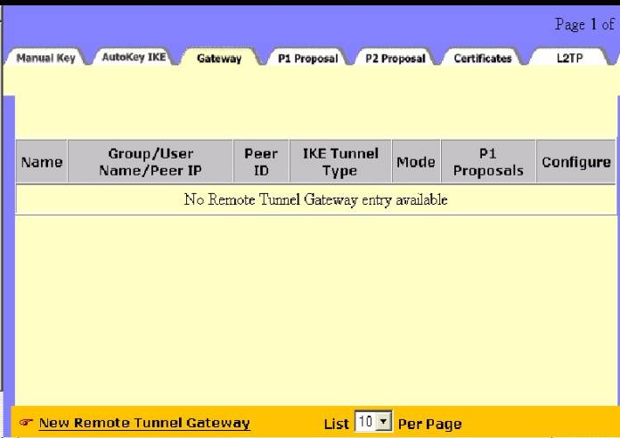
Notice that back
on the Gateway tab—the summary appears with a greenish background—this is
because no IKE configuration is associated with it yet—it will go clear when
we create the IKE-See figure #10
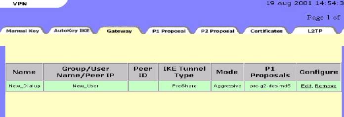
Figure #10
13. Now go to
the “AutoKey IKE” tab under the
VPN button and click on the “New
AutoKey IKE Entry” Link. See Figure
#11

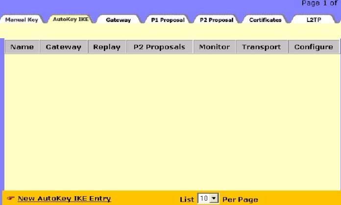
Figure #11
____________________________________________________________________________________
14. Now you can configure your AutoKeyIKE
a. Give the IKE a name (e.g. New_Dialup_IKE)
b. Make sure the “Remote Gateway” you just created is selected from the dropdown box.
c. Select your Phase 2 Encryption and Hash Algorithms (E.G. nopfs-esp-des-md5).
d. Note-“Enable Replay Protection”” can be selected here as well—but it must be selected on the NSR security policy as well if chosen. (Requires that each IKE negotiation have a sequence number—not to be used in HA).
e. Click OK to save the new “AutoKey IKE”—See Figure #12 Below Note: VPN Monitor is not an option with Dailup because it is not available on the client software.
Note:
Select a proposal for authentication (AH), or for encryption (and authentication) (ESP). For convenience, the NetScreen- comes with 8 predefined proposals for ESP. (You must create your own Phase 2 proposals for AH.) Each predefined SA features either "nopfs" or "g2" for key generation, DES or 3DES for encryption, and MD5 or SHA-1 for authentication.
1. nopfs - No Perfect Forwarding Secrecy (PFS). The key used in Phase 2 is derived from that used in Phase 1. PFS generates each new key independently from its predecessor, which increases security but also increases processing overhead.
2.g2 - Diffie-Hellman Group 2. In Phase 2, the participants renegotiate a new key using PFS.
3. des - Data Encryption Standard, a cryptographic block algorithm with a 56-bit key
4.3des - A more powerful version of DES in which the original DES algorithm is applied in three rounds, using a 168-bit key
5 .md5 - Message Digest (version) 5, an algorithm that produces a 128-bit message digest (or hash) from a message of arbitrary length. The resulting hash is used, like a “fingerprint” of the input, to verify authenticity.
6. sha-1 - Secure Hash Algorithm-1, an algorithm that produces a 160-bit hash from a message of arbitrary length. (It is generally regarded as more secure than MD5 because of the larger hashes it produces.)
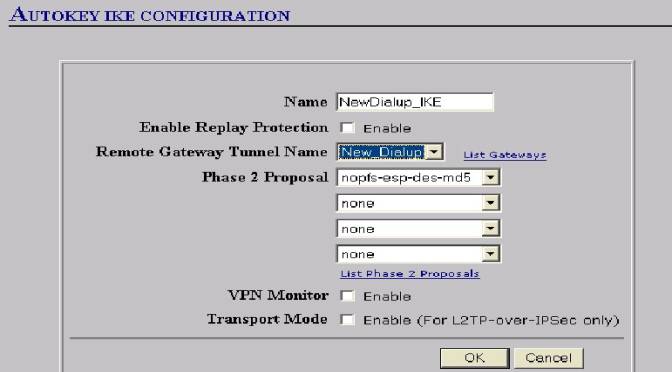
Figure #12
______________________________________________________________________________
15.
Notice that the “AutoKey IKE” overview tab now shows “green”
as the Remote gateway once did. You
will find that the Remote gateway no
longer is “green” since we have
created the “AutoKey IKE”.
Similarly, the “AutoKey IKE” will “go
clear” as soon as a VPN Policy is
created and associated with the AutoKey
IKE—see Figure #13
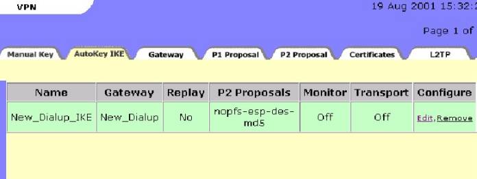
Figure #13
____________________________________________________________________________________
16.
 Go
to the “Policy” button; “Incoming Tab” and click on the New
Policy Link : (as show in figure #14)
Go
to the “Policy” button; “Incoming Tab” and click on the New
Policy Link : (as show in figure #14)
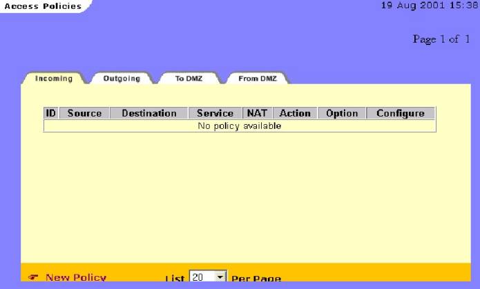
Figure #14
17. Configure the Policy as follows:
a. Give the policy a Name (This is optional and does not show up in the ACL display ).
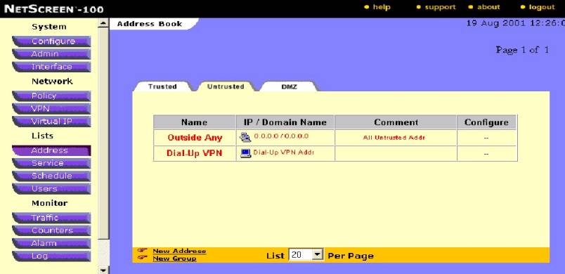
b.
Choose your source address from the
dropdown box as “Dialup VPN”
c. Choose your destination address from the dropdown box as the Trusted address book entry for your private network-(e.g.Trusted Lan)
d. Choose your desired service—Any is most common
e. Leave NAT Off—(Most cases).
f. Choose action of “Tunnel”
g. Choose VPN Tunnel—The AutoKey IKE you Created Previously(Name)
h. Enable elected options such as Logging(recommended); authentication, counting, scheduling, and traffic shaping options.
i. Save policy by selecting OK at the bottom of the screen.
See Figure #15:
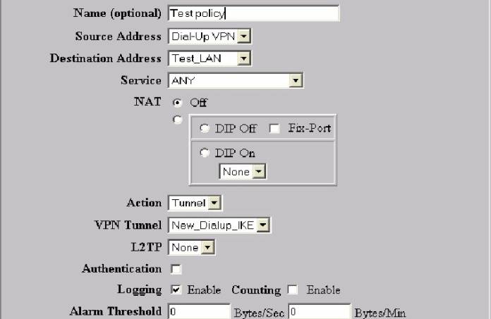
Figure #15
_______________________________________________________________________________
17.
One last
procedure needs to be attended to: If
the policy that you just created is “below” and existing
–“non-encrypted” policy00the “encrypted policy needs to be moved
“ahead” on any “non-encrypted “ policy. (See Figure #16)
The Access Control (policy) List or ACL is always read from the top down
and most restrictive policy toward the “top”.
There is nothing more “restrictive” than an “encrypted” or VPN
policy-so they must come first in the ACL by definition. Policy 5 must
“move” above policy 4

![]()
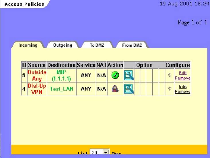
Figure #16
____________________________________________________________________________________
18.
Click on the “double arrow”: as
shown above to bring up the ‘Move” box; (See Figure #17)
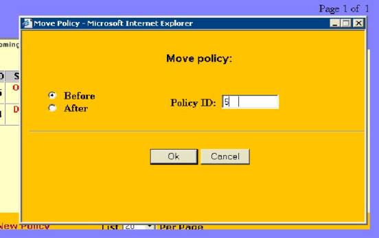
Figure #17
___________________________________________________________________
18.
By entering the policy ID(#5) to go before policy ID #4 and clicking “OK”-the
encrypted policy is move ahead of the non-encrypted one. The Result is as below
(see figure #18)
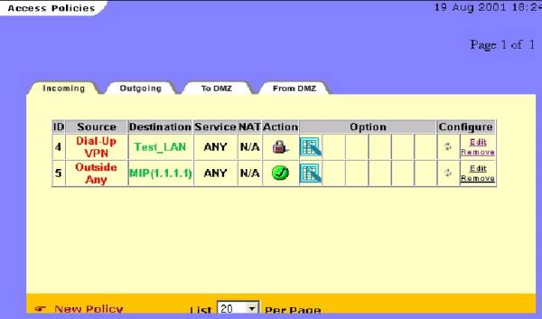
Figure
# 18
Special
Notes:
1.
Your
configuration for this Auto IKE VPN is now complete on the Netscreen End—You
can now proceed to configure the Client end of the VPN.
Once the Client end is configured and ready for testing—open a command
prompt on the client and “ping” any trusted address on the “IP Subnet”
or Trusted LAN—Remember that these hosts must have the Netscreen’s trusted
interface as their default gateway or a static route back to that address.
If pings are returned the VPN tunnel is up and successfully completed.
A continuous ping is best as it may take up to 5-6 packets to receive a
“return” ping to prove the tunnel is up: The prompt window should look
similar to Figure # 19 Below if it is successful. Note the continuous ping
switch is : “ping <IP address> -t “

Figure
#19
________________________________________________________________________
2.
If
you are using a “dialup” adapter connection, be sure that your Network
adapter (NIC) card does not have an IP address bound to it that is in the same
“IP subnet” that you are
dialing into—if it does have such an address the IPsec traffic will fail to go
through the tunnel and will attempt to route out the NIC adapter.
3.
Successful
traffic can be confirmed by looking in the “incoming” policy log on the
Netscreen device.
4.
With
Windows 2000 and using a
“dialup” connection you will have to enter the security policy after the
dialup connection is made in order to select the “PPP adapter” option.
It will not appear in the dropdown box until the connection is made in
Windows 2000.
5.
The
Netscreen IPsec client is strictly a Layer 3 device and does not include any
configuration options for normal Windows
Networking. These must be configured separately from the VPN configuration.
Help in setting the required Networking configurations can be obtained
from the Netscreen Knowledge Base. Name
resolution (Netbios), drive mappings, Domain
Logins, and accessing Domain Resources are not supported by Netscreen Technical
Assistance center.
6.
Notice
in the “right click” menu of the NSR icon in the system tray
(see Figure 1A) there is a Log viewer that the client provides with some
error message logging and system debug capabilities.
7.
Also
available on the “right click” menu
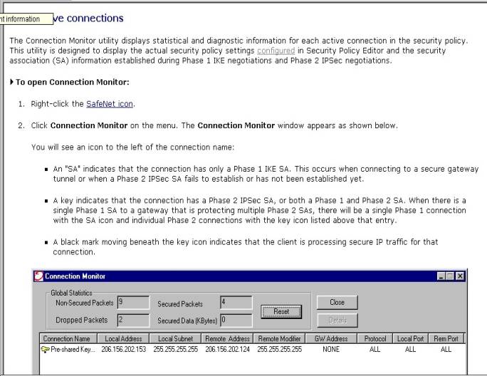
are a connection monitor, a log viewer , and an extensive “help” function
that explains the usefulness and detail of these functions. See following
figures 20 and 21.
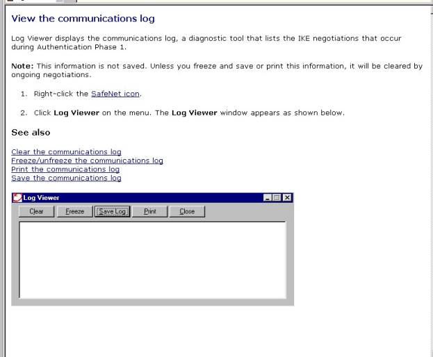
Figure
#20—Log viewer--from NSR help file

Figure
#21-Connection Monitor—from NSR Help files
8.
The
Netscreen’s Event log can also be useful in identifying connectivity and
configuration problems( see figure #22 Below):

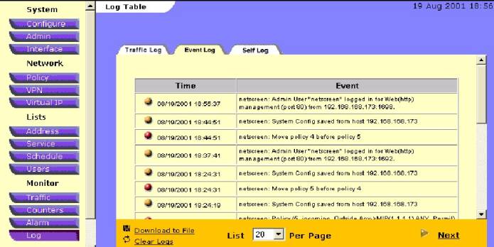
Figure
#22
Remote Klient IKE Konfiguration mit Pre-shared Key
To
configure the Netscreen Remote Security Policy Editor for a connection to a
Netscreen Firewall-Auto IKE Configuration with Pre-shared Key
(Shown is version 5.1.3 build 4)—August 17, 2001
______________________________________________________________________
Open your Netscreen Remote Security Policy Editor by right clicking on the NSR icon in the system tray and “activating” the security policy and then clicking on the “security policy editor” in the right click menu. (See Figure 1A below)
![]()
![]()
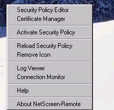
Figure 1A_______________________________________________________________
The image below(Fig. #1B) is a screen shot of what you should see once you open your security policy:
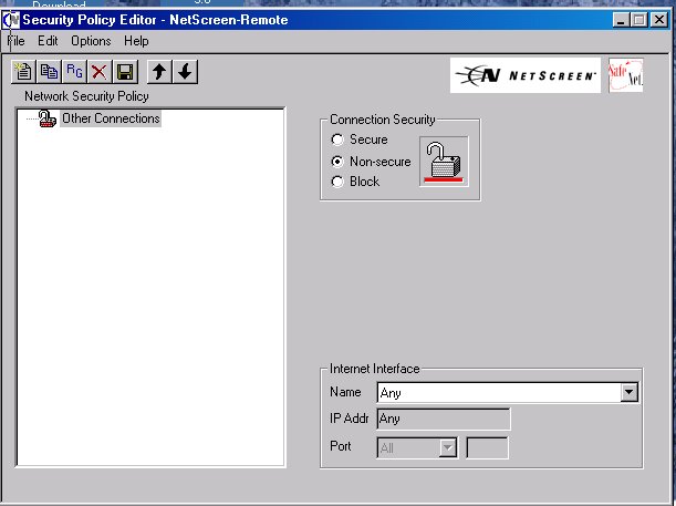
Figure
#1B
________________________________________________________________________
To start a new security policy:
Note:
If there is a previous connection already in
place simply perform the following checklists action item s as edits to the
existing policy.
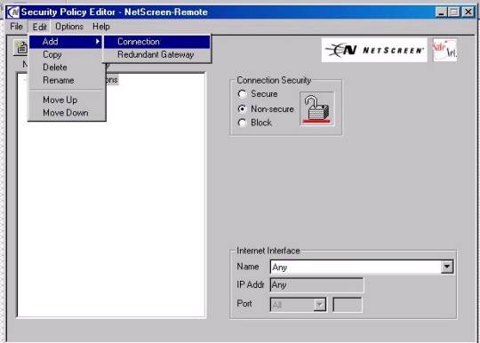
Figure
1C
_____________________________________________________________________
2. A “Green Lock” should appear in the display window called “new connection” as displayed below (Figure #2):
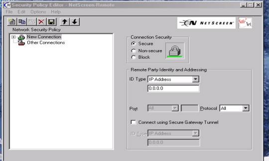
Figure #2
3. Expand out all the “Plus” signs until they appears as below (Figure #3)
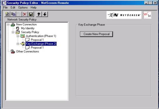
Figure
#3
You
are now ready to configure your Auto IKE VPN
To Configure an Auto Ike VPN:
Figure
#4
Note: You can “right click” the New connection heading when highlighted at any time and “rename” the selection to anything of your choice.
4. Configure this display as shown:
a. Connection Security should have “Secure” selected for the radio button.
b. Under Remote Parity Identity and Addressing:
1.
IP
subnet from the dropdown box for ID
type.
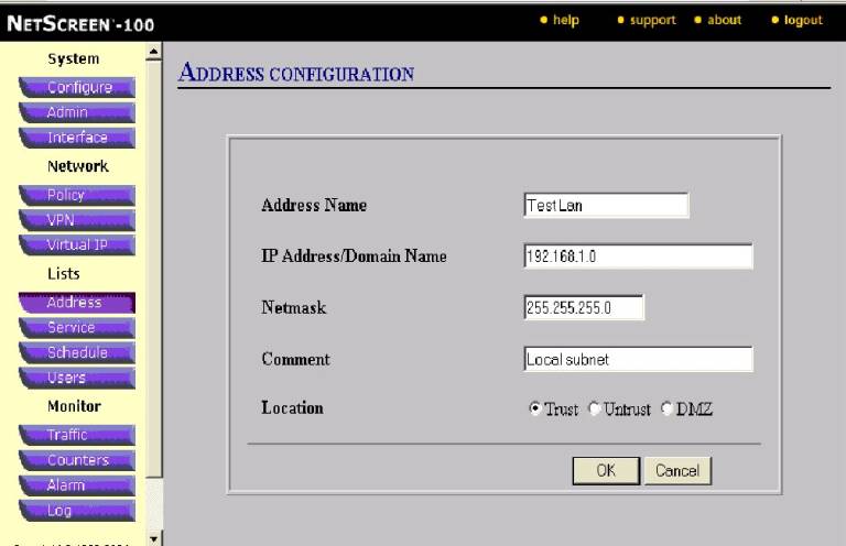
2. For Subnet input the Network address of your trusted LAN such as displayed below (192.168.1.0)
3. For Mask, input the subnet mask of your trusted subnet such as displayed (255.255.255.0) for example
4. Make sure that ‘Protocol” is set to ALL
5. Put a check in the box for “Connect using secure gateway tunnel”
6. For ID type choose IP address
7. In the box provided below IP address input the Untrusted interface (public)address of the Netscreen device your are VPNing to. (In this case it is 24.24.24.24).
8. At this point the display should be as shown below: (Figure #5)
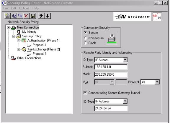
Figure
#5
________________________________________________________________________
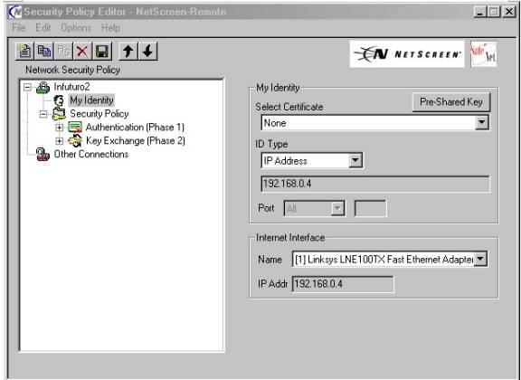
9. Now highlight heading “My Identity” and configure as follows:
(see Figure #6A) below:
a. Open the “Pre-shared Key” Button as shown below(arrow)
b. Input an Alpha numeric “Pres-hared Key” of between 8 and 54 characters. (No keyboard characters such as ?,!,@))-(see figure #6B)
c. Select Certificate should remain—“none”
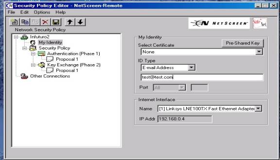
d.
ID Type should
be “Domain Name”, or “E-mail
Address”—Whichever you selected as the format for your Ike Identity when
you created your user on the Netscreen (see figure 6 C below)—example:
test@test.com
Note : The Ike ID types do not have to be “Real” E-mail addresses, domain names or IP addresses
e. In the “Internet Interface” dropdown box select the type of adapter with which you will connect—displayed is a Network interface card (NIC). This may also be a PPP adapter if connecting using a Modem connection. The IP Addr block will automatically be populated with the adapter’s IP address..
Figure
#6A
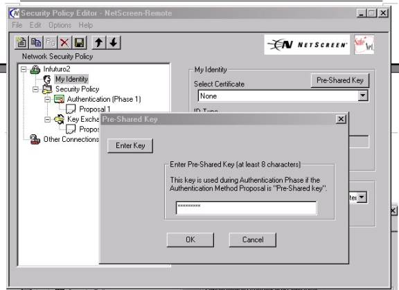

Figure #6B
________________________________________________________________________
______________________________________________________________________
Figure
6C
________________________________________________________________________
10. Now move to highlight the Heading Authentication Phase, subheading Proposal 1 (As shown in Figure #7 below)
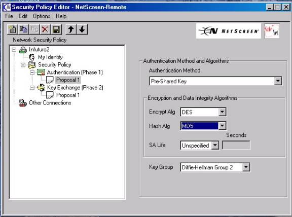
Figure
#7
_____________________________________________________________
11. Select Authentication Method—“Pre-shared Key”
12. Also select from the appropriate dropdown boxes your Phase 1 , Proposal 1
Encryption and Hash Algorithms—in this case its Des and MD-5—these
must match what you selected when you built you “Remote Gateway”
under the Netscreen’s VPN button, Gateway tab.
§ Encryption Algorithm. Select DES for minimal security or Triple-DES for highest security.
§ Hash Algorithm. Select MD5 for minimal security or SHA-1 for highest security.
Note:
Select a proposal for authentication (AH), or for encryption (and authentication) (ESP). Each predefined SA features either "nopfs"(Phase 2) or "g2" for key generation, DES or 3DES for encryption, and MD5 or SHA-1 for authentication.
A. nopfs - No Perfect Forwarding Secrecy (PFS). The key used in Phase 2 is derived from that used in Phase 1. PFS generates each new key independently from its predecessor, which increases security but also increases processing overhead.
B. g2 - Diffie-Hellman Group 2. In Phase 2, the participants renegotiate a new key using PFS.
C. des - Data Encryption Standard, a cryptographic block algorithm with a 56-bit key
D.3des - A more powerful version of DES in which the original DES algorithm is applied in three rounds, using a 168-bit key
E.md5 - Message Digest (version) 5, an algorithm that produces a 128-bit message digest (or hash) from a message of arbitrary length. The resulting hash is used, like a “fingerprint” of the input, to verify authenticity.
F. sha-1 - Secure Hash Algorithm-1, an algorithm that produces a 160-bit hash of arbitrary length.
13. Select the SA life—generally left “Unspecified” for Netscreen use, third party devices may require something else.
14. Now select the Key
Group—Your Choices are Diffe-Helleman
GP 2
( Most widely used or you can choose group 1 or group 5 )—this will be the
same as you chose in your Netscreen’s “Remote Gateway” setup—IE. “G2”
15. Now move to highlight under Key Exchange (Phase2), sub heading
Proposal 1 ( as shown in Figure #8 below):
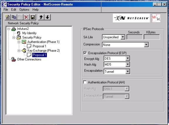
Figure
#8
16. Leave or set SA life as “unspecified”
17 .Leave or set Compression as “None”
18. Put a check in the ESP check box
19 Choose an Encryption security that matches what you selected in the “user” setup on the Netscreen device[Choices as DES(56 bit), 3DES (168bit) or Null (no encryption)]—for newcomers we recommend DES
20.Choose a Hash algorithm [choices are MD-5, SHA-1 or DES-MAC]-for newcomers we recommend MD-5.
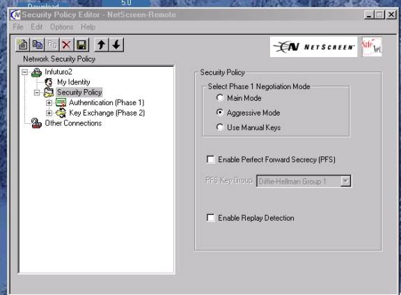
21.At this point if you have chosen either “PFS” or “Enable Replay Protection” as part of you “Auto IKE: configuration on the Netscreen—then you must proceed to highlighting the “Security Policy” heading and place a check in the appropriate checkbox.—(see figure #8B below).


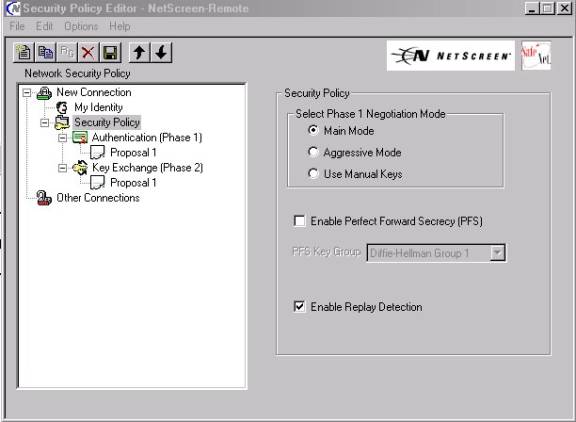
Figure #8B
___________________________________________________________________
22.Click on “File” and “Save Changes” to save the current configuration.
Special
Notes:
1.
Your
configuration for this Auto IKE VPN is now complete and ready for testing—open
a command prompt and “ping” any trusted address on the “IP Subnet” or
Trusted LAN—Remember that these hosts must have the Netscreen’s trusted
interface as their default gateway or a static route back to that address.
If pings are returned the VPN tunnel is up and successfully completed. A continuous ping is best as it may take up to 5-6
packets to receive a “return” ping to prove the tunnel is up: The prompt
window should look similar to Figure # 12 Below if it is successful. Note the
continuous ping switch is : “ping
<IP address> -t “
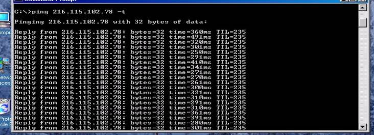
Figure
#9
________________________________________________________________________
2.
If
you are using a “dialup” adapter connection, be sure that your Network
adapter (NIC) card does not have an IP address bound to it that is in the same
“IP subnet” that you are
dialing into—if it does have such an address the IPsec traffic will fail to go
through the tunnel and will attempt to route out the NIC adapter.
3.
Successful
traffic can be confirmed by looking in the “incoming” policy log on the
Netscreen device.
4.
With
Windows 2000 and using a
“dialup” connection you will have to enter the security policy after the
dialup connection is made in order to select the “PPP adapter” option.
It will not appear in the dropdown box until the connection is made in
Windows 2000.
5.
The
Netscreen IPsec client is strictly a Layer 3 device and does not include any
configuration options for normal Windows
Networking. These must be configured separately from the VPN configuration.
Help in setting the required Networking configurations can be obtained
form the Netscreen Knowledge Base. Name
resolution (Netbios), drive mappings, Domain
Logins, and accessing Domain Resources are not supported by Netscreen Technical
Assistance center.
6.
Notice
in the “right click” menu of the NSR icon in the system tray
(see Figure 1A) there is a Log viewer that the client provides with some
error message logging and system debug capabilities.
7.
Also
available on the “right click” menu
are a connection monitor, a log viewer , and an extensive “help” function
that explains the usefulness and detail of these functions. See following
figures 13 an 14.

Figure
10—Log viewer--from NSR help file
Figure
11-Connection Monitor—from NSR Help files